What's this all about?
This page describes how to turn mains powered appliances on and off under computer control without risking killing yourself.
That last part is kind of important.
Links for source code downloads
Switch.cpp
Web Interface
More Detail
For the project I used a Raspberry PI computer to control three mains sockets. The sockets are controlled by radio signals, so they can be anywhere in the house.
Anything can be plugged into the sockets. In my case I use a bedside lamp in one, and I havent found a use for the other two yet.
The Raspberry PI runs a Linux OS, so a bit of linux knowledge was required to get things working. Now it's all set up, I have a simple web front end that I can use for general switching. Currently I still need the Linux command line to do any scheduling but I'm hoping to change that one day.
You'll also need to do a bit of soldering. Nothing difficult, just a few wires into PCBs.
Parts
Status Remote Control Power Sockets.
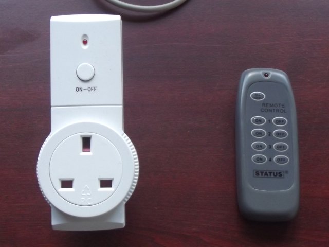
These came from Morrisons supermarket. I payed 5 quid for a pack of three of these sockets and the remote control. I expect there are a lot of similar ones on the market too.
Raspberry PI Computer.
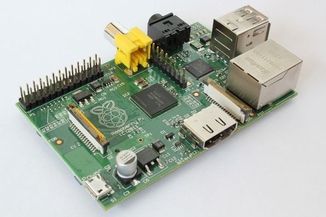
This is ideal for this kind of project for lots of reasons.
It only uses about a Watt of power so you can leave it switched on.
It has enough computing power to run a full Linux OS, which makes development easy.
It's very cheap, under Ł30.
It has some General Purpose IO. This means pins on the PCB that can be controlled in software to get signals in and out of it.
To run a Raspberry PI, you also need a 5V phone charger and an SD card. To be able to connect to it, I have it connected to my home router by an ethernet cable.
A Floppy Disk Drive Cable.
Sorry, I don't have a picture.
You can cut this up and use it for all of the wiring, and the connector to plug into the Raspberry PI.
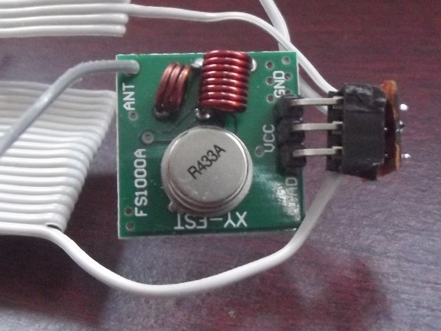
433MHz Transmitter and Receiver Modules
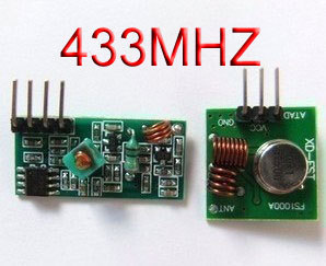
This may look complicated but it isn't as bad as it seems. You will need to solder the antenna wires onto these but it's an easy bit of soldering. These came from ebay, shipped from Hong Kong. Ł1.60 including postage and packing - I've no idea how they can do it that cheaply.
1M Ohm Resistor
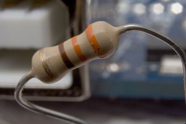
That's just a random picture of a resistor, not the actual 1M one I used. It's just to make sure I didn't blow up my laptop when recording the RC data.
Optional Items.
One IC socket.
This is to plug the pins of the transmitter into when connecting to the PI. One of the floppy cable connectors would also work.
One piece of stripboard 3 x 2 holes with the strips going the short way.
This allows you to connect the IC socket to the Floppy cable easier.
One Breadboard
This was used to plug the receiver into while capturing the remote codes. The floppy connector wold work thogh.
One 3.5mm socket.
I used this to connect my receiver (via the resistor) to 3.5mm cable. You could just wrap the wires around the plug though.
One 5V power supply.
This powered the receiver while capturing the codes. The Raspberry Pi has a 5V output that would do the job.
Temporary Items
One cable with a 3.5mm plug (headphone type) on each end.
I borrowed that from my speakers.
One PC.
I used a normal windows laptop. Anything with a soundcard that can record is ok.
Basically, anything to do with capturing the remote codes is only temporary.
Building the system
The code capturing system
Here's a picture of my code capturing setup.
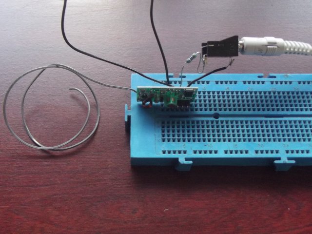
I made it as follows
Solder an antenna wire (the length is given in the receiver data) to the receiver module.
Plug the receiver module into the breadboard. You could use the flat end of the floppy cable here and adapt these instructions a bit.
Plug some bits of wire into the same strips on the breadboard where the Vcc and Gnd pins of the module are.
Solder one end of the resistor to the tip terminal of the 3.5mm socket. You could just wrap it tightly around the plug tip though.
Solder a piece of wire to the shield terminal of the socket. Wrapping it around the furthest bit of the plug from the tip wold work.
Connect the other end of the resistor to the data pin of the receiver.
Connect the other end of the wire you connected to the plug, to the GND of the receiver module.
Plug the other end of the 3.5mm cable into the mic socket of the laptop.
Connect the Vcc and Gnd wires to a 5V power supply. The +5V and Gnd pins of the Raspberry PI can be used as the power supply.
The transmitter system
Here's a couple of pictures of the transmitter and Raspberry PI
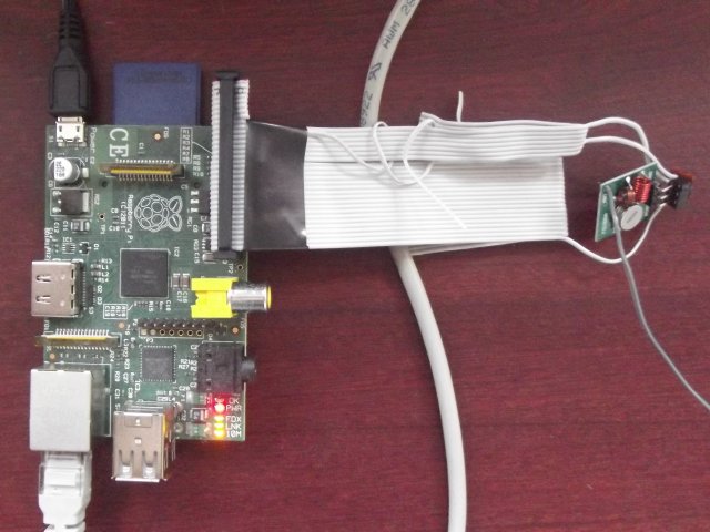
Please ignore the dodgy soldering on the IC socket.
I made this as follows
Cut the Floppy cable down to about 6 inches from the twisted end.
Check it will fit the raspberry pi with the twisted part nearest the PCB corner.
Untwist the twisted section of the cable so it all lays flat.
Cut off any wires going to the pins that are off the end of the Raspberry PI, these should be all but one of the section after the twist.
Find the wires that will be connected to +5V, Gnd and GPIO7.
+5V should be the 2nd from the top.
Gnd is 6th from the top.
GPIO7 is right at the bottom.
The next few instructions describe the IC socket and stripboard, you could use the other end of the floppy cable here instead.
Cut the IC socket down to just 3x1, for the transmitter to plug into.
Solder the IC socket into the small stripboard.
With the plug disconnected from the Raspberry PI, Solder the +5V, Gnd and GPIO7 wires to the stripboard in the correct places.
Solder an antenna wire to the transmitter module.
Plug the transmitter into the IC socket. Be careful to get it the right way.
Plug the floppy connector into the Raspberry PI.
Now you need the software, described later.
Capturing the codes
The software I used to cpture the codes was Audacity. It's free and lets you zoom right in to read the binary data from the waveform.
To capture a code, set audacity to capture at a high sample rate. I used 96000 per second, which is over the top, but better over than under.
With the power turned on to the receiver module, start recording. You should get a lot of random noise. Adjust the recording levels so it fills about half of the graph area.
Now press a button on the remote for your sockets. You should see a change on the wave display of Audacity. Stop recording and zoom in on the part where you pressed the button.
Here's a picture of what I got when zoomed right in.
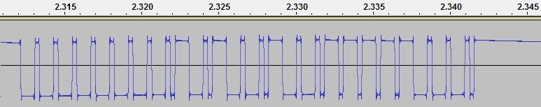
That pattern was repeated over and over for as long as I held the button down.
I noticed that the long pulses (up or down) were 3 times the length of the short ones. So I figured I could just transcribe it as so.
111110001000100010001000100010001000101110001011100010001011100010001011101110111011101110001000100010111111
With a bit of software (described later) I output that code at what seemed like the right speed through the transmitter to see if the socket did anything.
Nothing happened.
So, I ran audacity to capture the signal output from my system and saw this pattern.
000001110111011101110111011101110111010001110100011101110100011101110100010001000100010001110111011101000000
Which is exactly opposite to the one I captured from the remote control.
So, a quick change to the data I was sending to invert it all and I tried again.
This time the bedside lamp plugged into the socket came on.
So, a few minutes transcribing the codes for the other buttons on the remote control and I had a working system
Software
The software has to output the data strings captured above at the correct speed. In my case this was about 1kBit/Sec, but I don't expect all RC sockets to be the same.
1kBit/Sec is well within the capabilities of the Raspberry PI just a simple output/sleep loop. Faster rates may cause problems, I don't know as the only rate I've seen is 1k.
The software is based on the first GPIO example in C given here. I converted it (well re-named it) to c++ as it's easier to work with and changed the output to do what I needed, rather than just toggle the pins as it used to.
My source code is here. and can be built simply with g++ switch.cpp. BUT it directly accesses memory addresses and only root is allowed to do that. So, I developed it as root, then built it, named it "switch" and did a chmod +s switch to allow anyone to run it.
The program takes two arguments, the channel to switch, and whether to switch on or off. It figures out what code to send, and sends it ten times, just to make sure the socket hears it. The remote sends the code repeatedly until you release the button, but I thought 10 times seemed about right.
I also made a small web interface with a CGI script to call the switch executable, and a HTML file to show some buttons and call the CGI script. The whole /var/www folder for it and the web server config are here. It seems to work ok on a blackberry, and two different android devices. I keep it all behind a firewall though, as I don't want random people turning my lights on and off.
(c) 2012 Geoff Johnson.